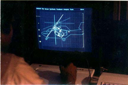
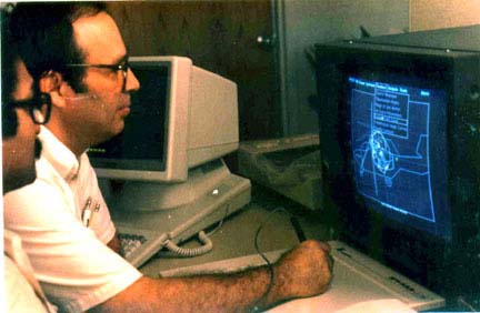
Shown here are some figures from the KINSYN7 system which was developed in the early 1980's by my company, KINTECH, Inc. Unfortunately, changes in the economy, competition from "copycat" competitors with cheaper though less powerful packages, and rapid cuts in the cost of computer display systems and computer hardware, forced us to abandon this work, even though we offered the most powerful mechanism design system in existence.
This system was developed in cooperation with The George Washington University School of Engineering and Applied Science. KINTECH purchased time on the engineering school's Vax 11/780 computer and Vector General and Megatek displays.
Programming was done by Murali Dandu Raju, a KINTECH employee at the time and a former G.W. student and by me. The first prototype system was developed for McDonnel Douglas Commercial Aircraft Division. The photos were taken for an article which Professor Ferdinand Freudenstein of Columbia University was preparing for Scientific American Magazine.
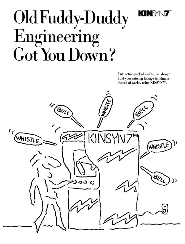
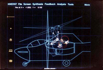
These photos showed KINSYN7 being used in a hypothetical design study such as might be involved in developing a new concept for a tilt-rotor aircraft. We theorized that the stability of a tilt-rotor aircraft could be enhanced by use of a mechanism to shift the engine towards the center of gravity as the rotor tilts. This motion is more complex than the simple rotation used in conventional designs.
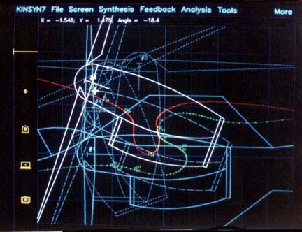
At the start of the design study, two required positions for the rotor were established. The reference position is shown solid and the alternate position dashed. In this figure, a tentative moving pivot attached to the engine cowling was chosen for a four-bar linkage. The red straight line shows the locus of all possible fixed pivots compatible with that choice of moving pivot. As the fixed pivot is moved along that locus, the link connecting the fixed and moving pivots is displayed in the two design positions of the rotor.
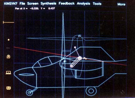
A second link completes the four-bar linkage. While scanning possible linkages, useful performance characteristics were simultaneously displayed on the screen by the KINSYN7 system. The "Grashof Type" of the mechanism was shown at the center of the bottom of the screen. The white box around the screen flashed on to indicate that the current linkage could move continuously through the given design positons without needing reassembly. The coupler curve which the instantaneously displayed linkage would generate was shown in red and green. It distorted continuously as the linkage was altered. The different colored branches showed where the double rocker linkage being viewed at that instant would lock up and the two arcs showed the limits of link travel.
Interaction with the computer was via a data tablet. The computer responded immediately, showing the curves or results pertinent to the newly entered constraints a fraction of a second after the user changed the specifications.
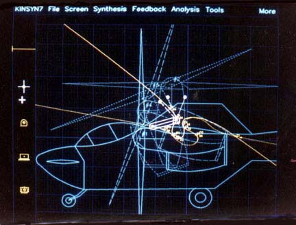
Moving the pen cursor to the words at the top of the screen caused a "menu" to pull down. Various synthesis options could then be turned on or off by pressing them with the pen. Shown is a menu allowing the user to turn on or off instantaneous feedback data such as transmission angle plots, coupler curves, ranges of link motion, and so forth.

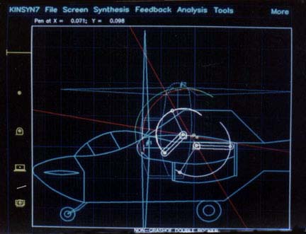
After introducing a third design position to more closely control the motion of the rotor, the (hypothetical) designer (moi) thought it might be possible to use a slider-crank mechanism to create the desired motion. On the left is shown a tentative crank capable of moving the rotor exactly through the three positions. On the right the computer is showing the circular loci of possible sliders for the given motion. The solid circle is the slider locus in the first design position and the dashed circles show the alternate positions of the loci. A tentative slide block is shown superimposed on the loci. Some of the poles and image poles associated with the motion have also been chosen for display.
Adding a fourth design position has reduced the number of possible locations for fixed or moving pivots. There is now a pair of cubic curves which show where the pivots must lie. These "Burmester" curves are shown in yellow. There is a one-to-one correspondence between the possible moving pivots on the dotted curve and the possible fixed pivots on the solid curve. As one scanned along these curves, the four positions of the link under consideration were shown, allowing one to judge the space requirements, swing angles, and timing sequence.
Here one of the four design positions was being altered. The Burmester curves are shown in color and squirmed around on the display in "real time" as the positions were adjusted. The locus of possible moving pivots is shown in green and the locus of possible fixed pivots is shown in red.
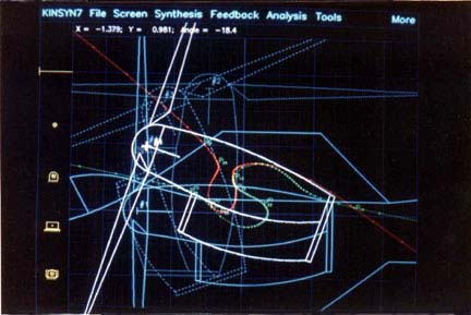
Notice that a slight change in the fourth design position has made a major change in the shapes of the Burmester curves and in the possibilities for locating the pivots on the rotor or the fuselage.
Here, a time exposure of the animation of one of the synthesized linkages is shown. Animation of the linkage allowed the designer to judge the kinematic performance of the mechanism in actual operation. Displays of data such as velocity relationships, transmission characteristics, or coupler curves could also be instantaneously obtained.