Subband Coding
Abdou Youssef
-
Motivation
-
Linear Filters
-
Low-Pass Filters (LPF)
-
High-Pass Filters (HPF)
-
Examples of LPF's and HPF's and their Effect
-
The Main Scheme of Subband Coding
-
Illustration of Subband Coding on 1D Signals
-
Issues
-
Filter Design
-
The Perfect Reconstruction Condition
-
Examples of Good and Bad Filters that Satisfy PR
-
Quantization in Subband Coding
-
Vector Quantization of Subbands
-
Shape of the Decomposition Tree
-
Same or Different Filters for Different Subbands?
Back to Top
1. Motivation
- Problems with DCT-based compression
- Blocking artifacts, especially at low bitrate
- The methods for reducing blocking artifacts, such as
overlapped transforms, are costly and complicated
- Applying DCT on the whole image, rather than on small
blocks, ignores the significant differences in frequency
contents in various regions of the image, thus leading to less
quality-bitrate performance
- Advantages of wavelets/subband coding
- They operate on the whole image as one single block
- Thus avoiding blocking artifacts
- While dynamically adjusting the spatial/frequency resolution
to the appropriate level in various regions of the image
- In practice, wavelets/subband coding performs as well as DCT
and sometimes better, especially at low bitrate
Back to Top
2. Linear Filters
- Definition of a linear filter
- Let
 and
and  denote the Fourier Transforms of
  and
and  , respectively
- Theorem:

Back to Top
3. Low-Pass Filters (LPF)
- An LPF eliminates the high-frequency contents of any input
signal, and preserves the low-frequency contents
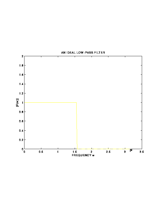
- An ideal LPF
 must then have its Fourier Transform
  as a
nonzero constant in a frequency range
  , and zero in
the remaining range
 ![$[a,\pi]$](img13.gif)
- Applications: Noise removal and image smoothing
Back to Top
4. High-Pass Filters (HPF)
- High-pass filters (HPF)
- A HPF eliminates the low-frequency contents of any input
signal, and preserves the high-frequency contents
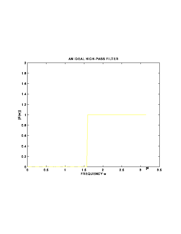
- An ideal HPF
 must then have its Fourier Transform
  equal to zero
in a frequency range
  , and equal to a nonzero constant
in the remaining range
 ![$[a,\pi]$](img13.gif)
- Applications: Sharpening and edge detection
- Ideal LPF's and HPF's are not realizable in practice, but many
realizable filters are good approximations of ideal filters
- A filter is called a finite-impulse-response (FIR) filter
if has a finite number of taps; otherwise, the filter
is called an infinite-impulse response (IIR) filter
Back to Top
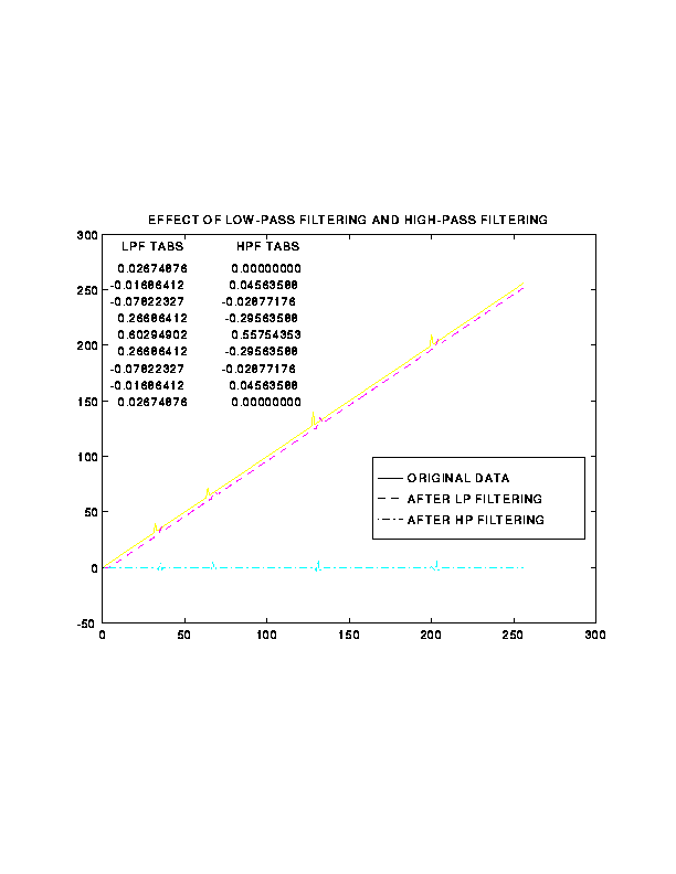
5. Examples of LPF's and HPF's and their Effect
Back to Top
6. The Main Scheme of Subband Coding
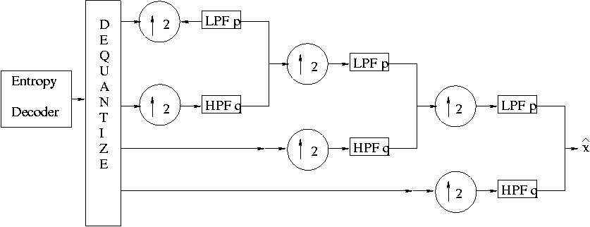
- The General Subband Coding/Decoding Scheme

- How Subband Coding Is Generally Applied: a Tree-Like Structure
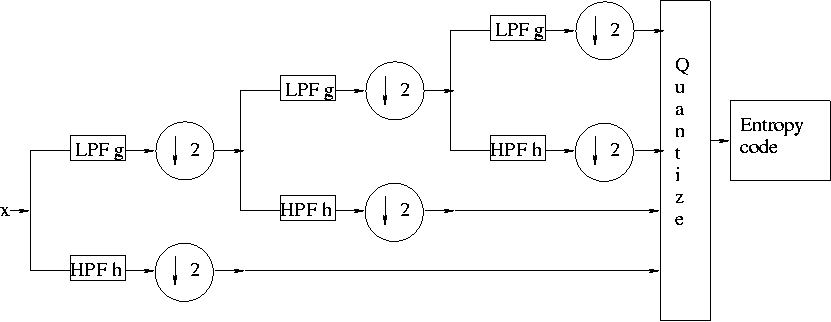
- The Corresponding Decoder Structure
Back to Top
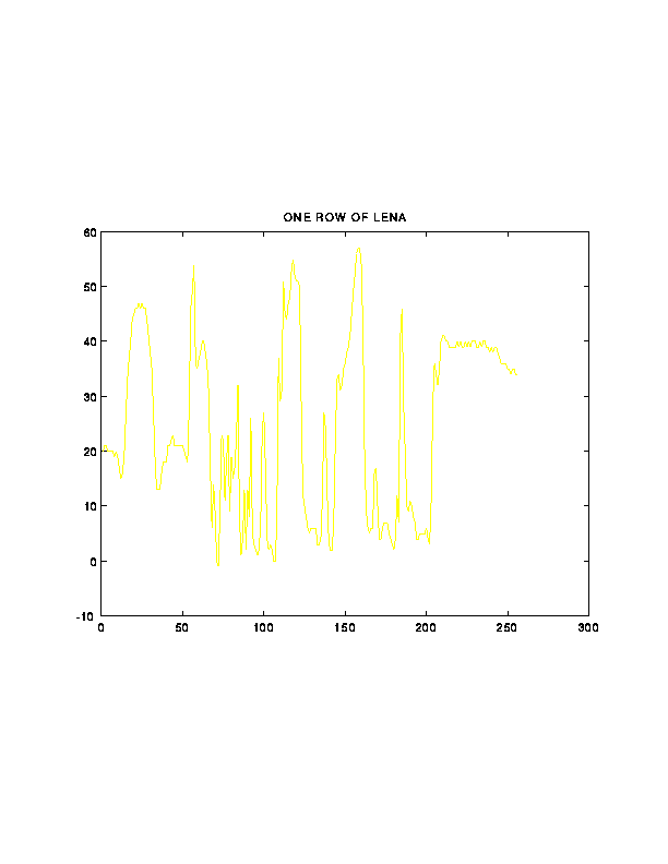
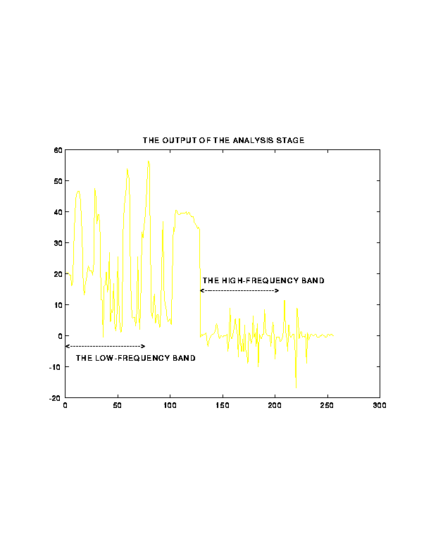
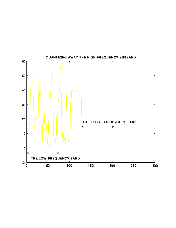
7. Illustration of Subband Coding on 1D Signals
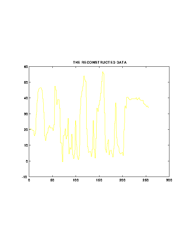
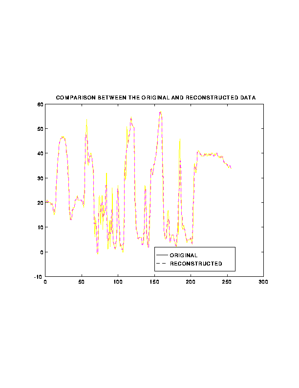
Back to Top
8. Issues
- Filter design
- Quantization Method
- Shape of the tree
- Same or different filter sets per image or class of images?
Back to Top
9. Filter Design
- Classical filter design techniques for LPF's and HPF's
- Least Mean Square technique
- Butterworth technique
- Chebychev technique
- Those techniques are for designing single filters, rather than a
bank of four filters working together
- The four filters for a subband coding system must have the
perfection reconstruction property
- the output signal is identical to the input signal if
no quantization takes place
Back to Top
10. The Perfect Reconstruction Condition
- The z-transform of a sequence
 is
is

- If
 is the output of a linear filter
  given input
 , then
- Therefore, for the subband coding scheme
- To have
 , we must have
 , leading to the following
perfect reconstruction (PR) condition:
- Consequently, to get a subband filter bank (of four filters), one has
to solve the two equations above, subject to the constraints that
Back to Top
11. Examples of Good and Bad Filters
that Satisfy PR
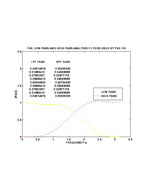
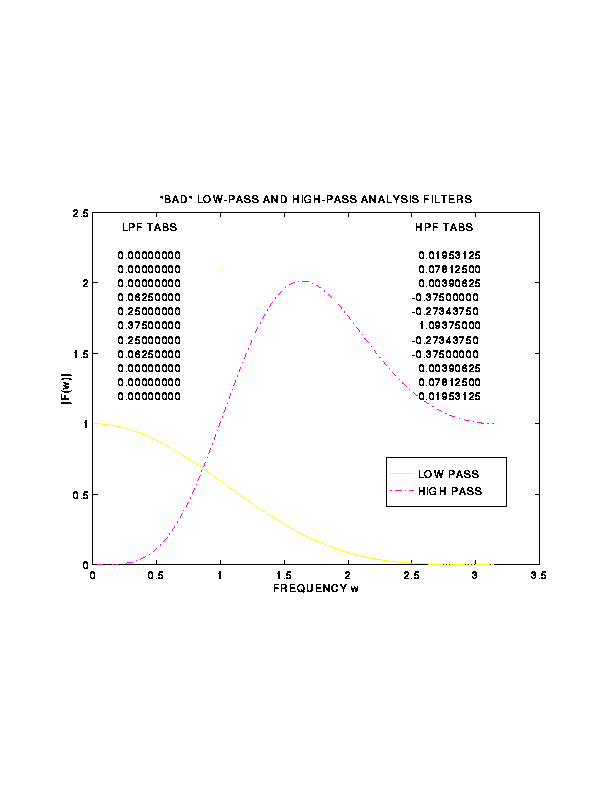
Back to Top
12. Quantization in Subband Coding
- Quantization approaches of the subbands
- Uniform scalar quantization
- Non-uniform scalar quantization
- Vector quantization
- One quantizer for all the subbands, or
- Different quantizers for different subbands
- Prospects for optimal Max-LLoyd scalar quantization of high-frequency
subbands
- Probability distribution of the pixel values in HF subbands:
The generalized Gaussian distribution
where
and  is the standard deviation of the underlying data
- Experimentation has shown that
 is about
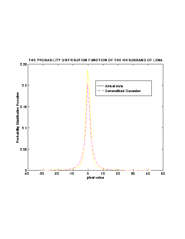
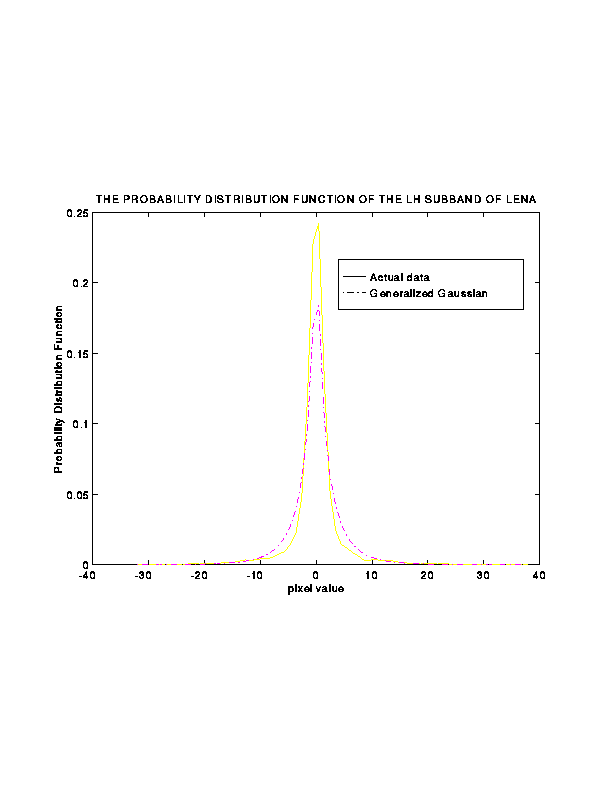
- Therefore, the sender need not send the decision levels and
reconstruction levels
of the Max-Lloyd quantizer; rather, only the standard deviation
 need be sent.
Back to Top
13. Vector Quantization of Subbands
- Is VQ needed for high-frequency subbands?
- Answer: It depends of how good the filters are
- Under ideal filters, the high frequency coefficients
are completely decorrelated, making VQ unnecessary
(and rather undesirable)
- In practice, the farther the filters are from ideal,
the more correlation ``leaks'' into the high-frequency
subbands, thus opening the door for VQ
- With the commonly used filters, there is
some correlation leakage; but there is still the tradeoff
between the slight improvement brought by VQ and
the high time overhead associated with VQ
- Design Issues for VQ in subband coding
- One VQ table for all subbands, or
- One VQ table per subband, or
- One VQ table for the subbands of a whole class of images?
- How large should the vector size be?
Back to Top
14. Shape of the Decomposition Tree
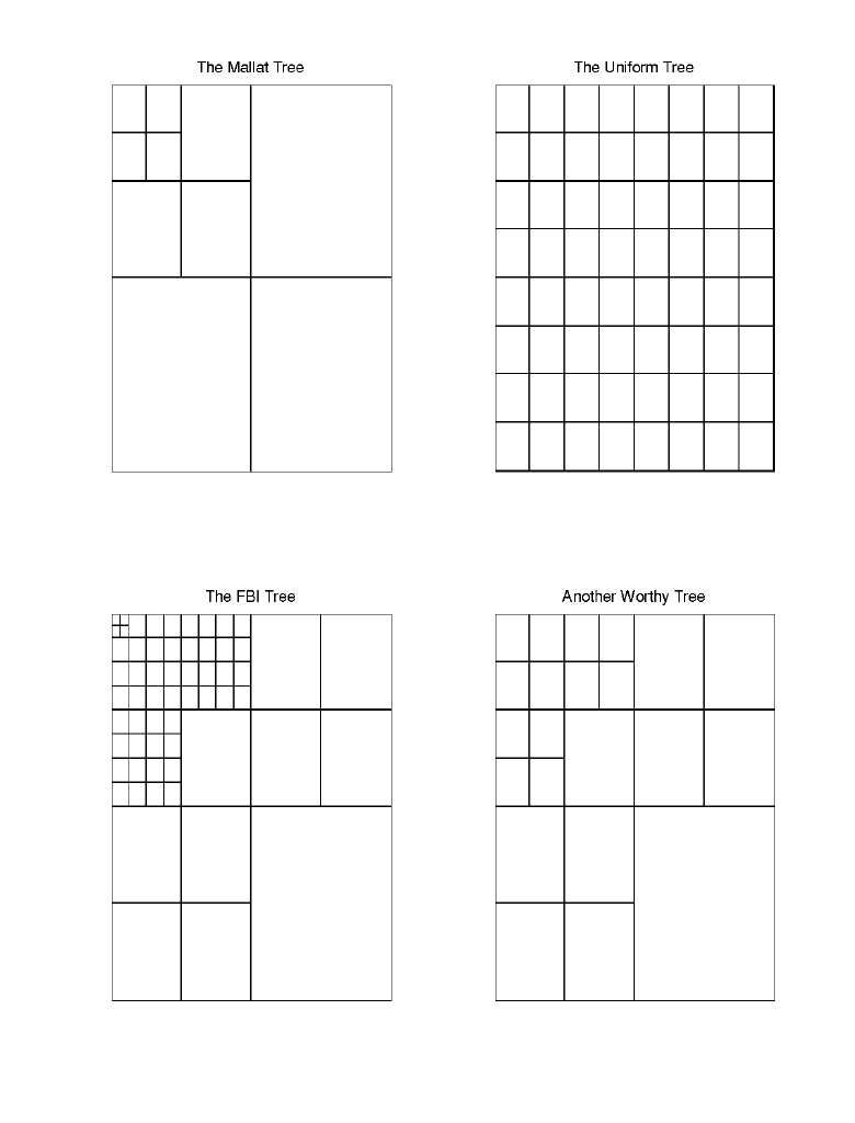
- Questions about the tree shape:
- What is the best shape?
- Is there a best shape for all images, or at least one best shape per class of
images?
- If not, is there an efficient way of deciding the shape of the tree on-line?
Back to Top
15. Same or Different Filters for Different Subbands?
- Intuitively, the best filter set for a given signal is the one whose
corresponding wavelet best resembles the signal in shape (i.e., in plot)
- The data in the subbands have different plots than the original data,
suggesting the use for different filters than the ones applied on the
original data
- For better understanding of this issue, one has to draw on the
insight provided by wavelet theory, which is the subject matter of next lecture
Back to Top
 is characterized by a sequence
  of real numbers; the
  's are called the filter taps
 through filter
  gives an output signal
  where
where


![]()


![]() is the standard deviation of the underlying data
is the standard deviation of the underlying data
![]() is about
is about ![]()


![]() need be sent.
need be sent.
